Drawing of Propeller Planes Pulling
A propeller is a rotating fan-like structure that is used to propel the ship by using the power generated and transmitted by the main engine of the ship.
The transmitted power is converted from rotational motion to generate a thrust which imparts momentum to the water, resulting in a force that acts on the ship and pushes it forward.
A ship propels on the basis of Bernoulli's principle and Newton's third law. A pressure difference is created on the forward and aft side of the blade and water is accelerated behind the blades.
The thrust from the propeller is transmitted to move the ship through a transmission system which consists of a rotational motion generated by the main engine crankshaft, intermediate shaft and its bearings, stern tube shaft and its bearing and finally by the propeller itself.
A ship can be fitted with one, two and rarely three propellers depending upon the speed and manoeuvring requirements of the vessel.
Material and Construction of Propeller
Marine propellers are made from corrosion-resistant materials as they are made operational directly in seawater which is a corrosion accelerator. The materials used for making marine propellers are an alloy of aluminium and stainless steel.
Other popular materials used are alloys of nickel, aluminium and bronze which are 10~15 % lighter than other materials and have higher strength.
The construction process of the propeller includes attaching a number of blades to the hub or boss by welding or forging in one piece. Forged blades are highly reliable and have greater strength but are expensive as compared to welded ones.
A marine propeller is constructed by sections of helicoidal surfaces acting together to rotate through the water with a screw effect.
Types of Propeller
Propellers are be classified on the basis of several factors. The classification of different types of propellers is shown below:
A) Classification by Number of Blades Attached:
Propeller blades may vary from 3 blade propeller to 4 blade propeller and sometimes even 5 blade propeller. However, the most commonly used are 3 blades and 4 blade propellers.
However, the most commonly used are 4 blades and 5 blade propellers.
The propeller efficiency will be highest for a propeller with a minimum number of blades i.e. 2 blade propeller. But to achieve strength factor and considering the heavy loads subjected by the ship, sea and weather two-blade propellers are not used for merchant ships.
3 Blade Propeller
A 3 blade propeller has the following characteristics:
- The manufacturing cost is lower than other types.
- Are normally made up of aluminium alloy.
- Gives a good high-speed performance.
- The acceleration is better than other types.
- Low-speed handling is not much efficient.
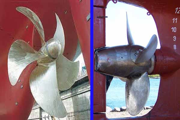
4 Blade Propeller
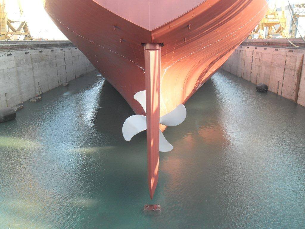
Photo Credits: Capt. Sagar
A 4 blade propeller has the following characteristics:
- The manufacturing cost is higher than the 3 blade propellers.
- 4 blade propellers are normally made up of stainless steel alloys.
- Have better strength and durability.
- Gives good low-speed handling and performance.
- Has a better holding power in rough seas.
- 4 blade propeller provides a better fuel economy than all the other types.
5 blade propeller
A 5 blade propeller has the following characteristics:
- Manufacturing cost is higher of all.
- Vibration is minimal from all the other types.
- 5 blade propellers have better holding power in rough seas.
6 blade propeller
- Manufacturing cost is high
- Vibration is minimal from all the other types.
- 6 blade propellers have better holding power in rough seas.
- With a six-blade propeller, the induced pressure field over the propeller decreases
Large container ships are mainly fitted with 5 or 6-bladed propellers.
B)Classification By pitch of the blade:
Pitch of a propeller can be defined as the displacement that a propeller makes for every full revolution of 360 ̊. The classification of the propellers on the basis of pitch is as follows.
Fixed Pitch Propeller
The blades in the fixed pitch propeller are permanently attached to the hub. The fixed pitch type propellers are cast and the position of the blades and hence the position of the pitch is permanently fixed and cannot be changed during the operation. They are normally made from copper alloy.
Fixed pitch propellers are robust and reliable as the system doesn't incorporate any mechanical and hydraulic connection as in Controlled Pitch Propeller (CPP). The manufacturing, installation and operational costs are lower than the controlled pitch propeller (CPP) type. The manoeuvrability of the fixed-pitch propeller is also not as good as CPP.
These types of propellers are fitted in a ship that does not have good manoeuvrability requirements.
Controllable Pitch Propeller
In a Controlled Pitch type propeller, it is possible to alter the pitch by rotating the blade about its vertical axis by means of mechanical and hydraulic arrangement. This helps in driving the propulsion machinery at constant load with no reversing mechanism required as the pitch can be altered to match the required operating condition. Thus the manoeuvrability improves and the engine efficiency also increases.
This drawback includes the possibility of oil pollution as the hydraulic oil in the boss which is used for controlling the pitch may leak out. It is a complex and expensive system from both installation and operational points. Moreover, the pitch can get stuck in one position, making it difficult to manoeuvre the engine.
Read Also: Controllable Pitch Propeller (CPP) Vs Fixed Pitch Propeller (FPP)
However, the propeller efficiency for the CP propeller is slightly lower than the same size FP propeller due to the larger hub to accommodate the blade pitch mechanism and pipings.
Propeller Dimension: As a general rule, a larger diameter propeller will be more efficient. But the real dimension of the propeller will depend on the type of ship it will be used for and the following factors:
- Aft body construction and design of the ship
- Clearance requirement between the tip and hull of the ship
- General ballast condition of the ship. For tankers and bulkers, the propeller size will be small as compared to containers
- The design draught of the ship
Propeller dimension approximate value
- For Container ship d/D = 0.74
- For Bulk carrier and Tanker d/D = 0.65
Where d- diameter of propeller, D- design draught
How does a ship propeller work?
For vehicles running on land, the propelling system which drives them is different. In those systems, the engine powers the shaft which is attached to the vehicle tyre to move ahead of the body of the vehicle. However, for ships which are displaced in water, there are no such tyres or surfaces where they can ride.
The ship is displaced in the water and the propeller is used to drive the ship ahead or backwards, depending upon the direction of rotation or pitch of the propeller. The engine of the ship is connected to the propeller of the vessel via shaft arrangement.
As the engine rotates the propeller, the radiating blades which are set at a particular pitch form a helical spiral, similar to a screw. While doing this, it transforms the power of rotation into thrust which is linear in nature.
This linear thrust will act upon water such that as the propeller blades rotate it creates the pressure between the surface in front and back of it. Hence, a mass of fluid is accelerated in one direction creating a reactive force that helps the body attached to the propeller (which is the ship) moves ahead.
For the ship to move in the reverse direction, the engine and hence the propeller is rotated in an anti-clockwise direction. This will reverse the thrust and the ship will move astern. However, the engine of the FP-propeller is always designed for clockwise rotation when sailing ahead, hence, prolong operation in astern direction is not efficient.
For ships fitted with CP propeller, the engine direction is not affected hence astern efficiency of the ship is better than that of a fixed-pitch propeller.
Types of Propeller Shaft
The ship engine is connected to the propeller via different shafts connected together, which can be named as:
- Thrust Shaft
- Intermediate Shaft
- Tail Shaft
Thrust shaft:
The crankshaft of the engine is first connected to the thrust shaft which passes through the thrust bearing whose main function is to transfer the thrust to the ship's structure. The casing of the thrust bearing is similar in construction to that of the main engine bedplate and the bearing is lubricated by main engine lubrication system oil. The material of the thrust shaft is usually solid forged ingot steel.
Intermediate Shaft:
The thrust shaft is then connected to a long intermediate shaft which comes in parts and is joined together using solid forged couplings . The length and number of intermediate shafts joined together depends on the location of the main engine as a larger ship will have more distance between the main engine and the propeller. The material of the intermediate shaft is usually solid forged ingot steel.
Tail Shaft:
The Tail shaft, as the name suggests, is the end part of the shafting arrangement and carries the propeller. The tail shaft itself is carried on a lubricated stern tube bearing with seals as it connects and protrudes out of the ship's engine room into the open sea, carrying the propeller.
The lubrication system can be of oil-based or water type. The tail shaft transmits the engine power and motion drive to the propeller. The material of the tail shaft is usually high strength duplex stainless steel alloy.
Reason for Heavy Running of Propeller
A propeller is supplied with engine power to rotate and propel the ship in the desired direction. If the amount of power provided to the propeller is not generating the same rate of revolution, the propeller is considered to be in a heavy running state which may be due to the following reason:
- Damage to propeller blades
- Increase in hull resistance due to hull fouling resulting in a change in wakefield
- During rough / heavy seas
- Ship sailing against the current
- Ship sailing in light ballast condition
- Ship Sailing In Shallow Water
- Ship with a flat stern
References:Q & A on marine diesel engine by Stanley g. & Naval architecture by Reeds
You might also like to read:
- Understanding Propeller Hubs: Design, Functioning, and Maintenance
- Marine Propeller Shaft: Design And Construction
- Understanding Design Of Ship Propeller
- 10 Factors Considered For Efficient Ship Propeller Design
- 8 Biggest Ship Propellers in the World
Disclaimer: The authors' views expressed in this article do not necessarily reflect the views of Marine Insight.Data and charts, if used, in the article have been sourced from available information and have not been authenticated by any statutory authority. The author and Marine Insight do not claim it to be accurate nor accept any responsibility for the same. The views constitute only the opinions and do not constitute any guidelines or recommendation on any course of action to be followed by the reader.
The article or images cannot be reproduced, copied, shared or used in any form without the permission of the author and Marine Insight.
Tags: controllable pitch propeller propeller design ship propeller
Drawing of Propeller Planes Pulling
Source: https://www.marineinsight.com/naval-architecture/propeller-types-of-propellers-and-construction-of-propellers/

0 Response to "Drawing of Propeller Planes Pulling"
Post a Comment